The term “Direction” or “Directivity” originated among audiophiles and music lovers in the 1970s. It was then that people first started talking about the fact that audio cables and wires that are symmetrical from the physics point of view are actually not symmetrical at all and somehow change the sound of the audio system when changing the direction of their inclusion. Up until the mid-2000s, it was believed that directivity was a feature of only electrical conductors and most people were confident that the direction of the conductors matters just in signal circuits. However, advanced audiophiles have even oriented the power cables, choosing the right position of the plug in the socket in which the music sounds better. They were considered crazy by almost everybody. The orientation of the conductors in the amplifiers and explanations of the reasons for choosing a particular direction were rather haphazard for many years, in 2005, the orientation of the conductors in the signal circuits and power supply circuits of the amplifiers was finally systematized.
Systematization of directions, along with the selection of components according to special criteria and the use of an extreme simple design allowed you to create an unusual Testing Audio System (TAS), which made it possible to determine the musical properties of individual radio components and wires with unattainable accuracy. It quickly became clear that the direction of the preferred sound of the components almost never coincides with their long side. Even for wires that have an unusually large length-to-thickness ratio, the best sound has always been achieved by touching certain points on the side surfaces. To describe this state of affairs, the term Vector Directivity was introduced.
Terms:
Vector Directivity – is a term that shows that Directivity is a three-dimensional, and not a linear (one-dimensional) phenomenon, as it was previously thought.
Vector Orientation – connecting components of audio systems, taking into account the directions of their vectors.
Internal (Innate) Vector (IV)- is a Vector formed during production (metal, plastic) or birth (wood, stone) of the material from which the component is made. see Forming the Vector.
The Surface Vector (SV) – is an additional vector of lower strength and significantly lower stability to the Innate one. SV consist of several simple vectors that gradually appear during mechanical processing, chemical reactions (oxidation), painting and varnishing of the surface.
Vector – is a line segment passing through the body of the component, starting at a certain entry point on the surface of the component and ending at a certain exit point on the other surface. Vector describes the three-dimensional direction of a component – its entry and exit points (surfases), using which it is possible to achieve the clearest sound when using a component in an audio system. The total vector of the component is equal to the vector sum of IV and SV and changes over time due to the drift of the force and direction of the SV.
Rotation vector (RV) – determines the progressive and tangential direction of the coil winding relative to the longitudinal direction of the part on which the coil is wound see below.
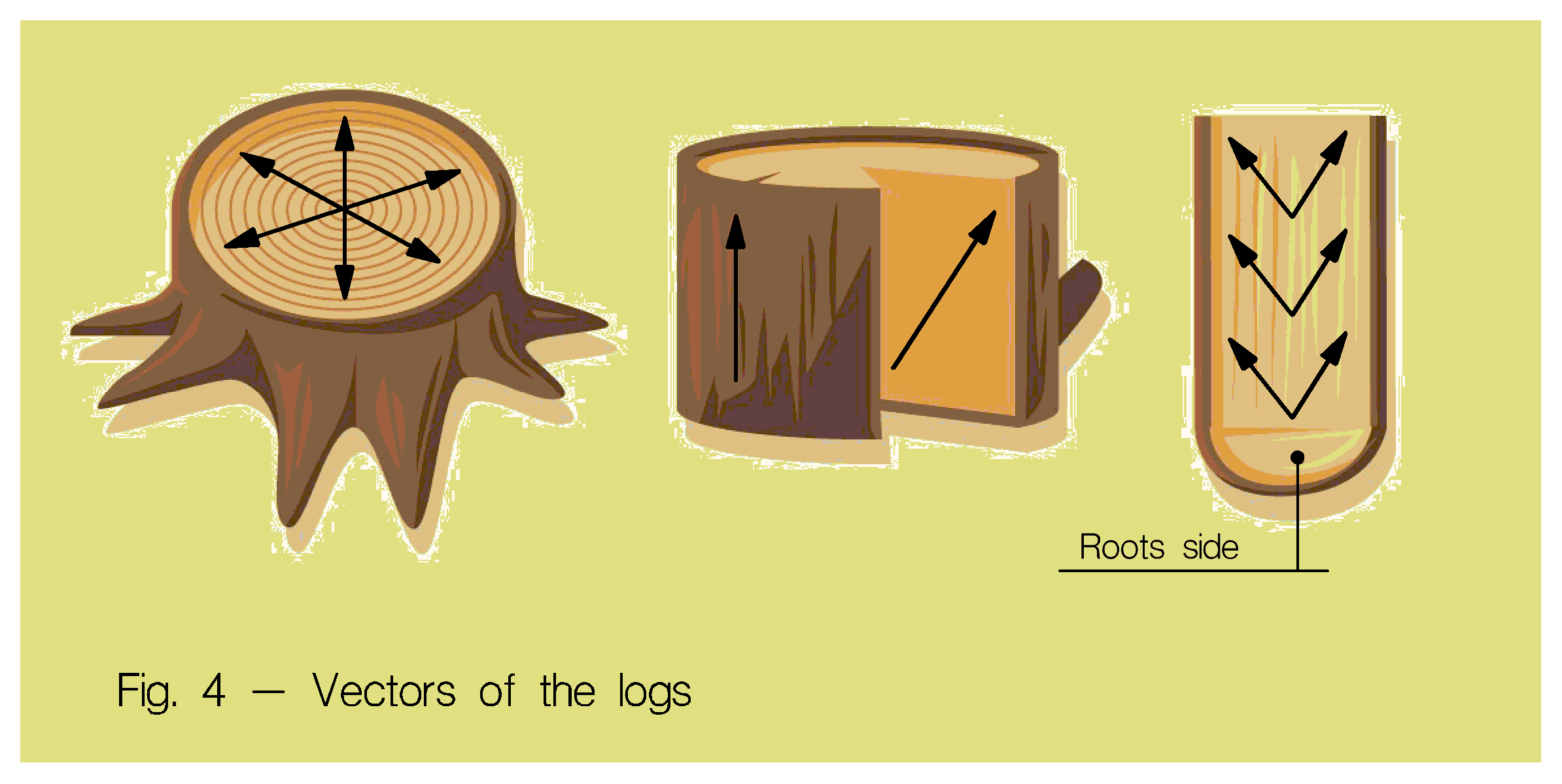
Radius Vector – the radial projection of the Vector formed in multilayer inductors and rolls of capacitors, see below. In nature, it is inherent in all plants (see Fig. 4).
Vector Phantom – The vector \overline{AB} that intersects the air space created between the points A and B during the shape change of the part. Read more here.
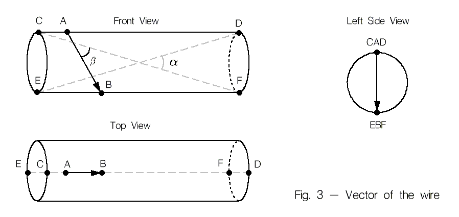
Vector Losses – deterioration of the sound clarity of the audio track, associated with inaccurate compliance with the vector orientation of its components during installation. The losses depend on the value of the angle \beta Fig. 3 between the vector and the line drawn between the points of connection of the component to the electrical circuit.
Vector Field – is a field of unknown nature that forms the vector direction of metals and dielectrics at the moment of their transition from the liquid state to the solid state. The presence of a vector field has been inferred hypothetically.
Clarity – wherever the opposite is not indicated, Musical Clarity is meaned, it is a subjective (non-physical) characteristic of the sound that closely intersects with the concept of sound-carrying that is a criterion from the vocabulary of violin makers and specialists in room acoustics. The loss of Clarity increases with the addition of each new component, wire, or inaccurate connection in a system, so Clarity is the only stable guide when choosing the correct direction of the component.
Coloration – is the emphasizing (or darkening) of certain areas of the frequency range of the sound that is marked by our perception. Each component of the audio system has its own unique coloration. The overall coloration of the system is a kind of chorus, consisting of individual colorations of each component and each piece of wire. for more information, see here.
Determining the direction of the vector
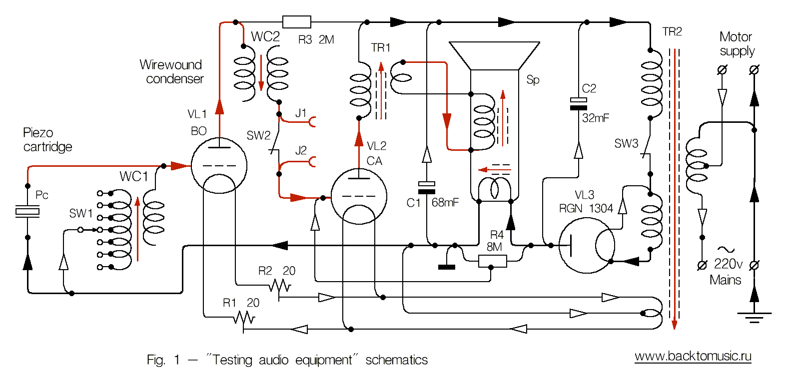
The classical method: the tested component is included in the break of the signal circuit of the Testing Audio System (TAS) in several different ways, changes in the sound of the system are evaluated by ear and the clearest take is selected. The signal circuit is closed through the test component’s body by means of long test probes J1 and J2 (see schematic diagram in Fig.1), installed in the connection gap between wire capacitor WC2 and power triode grid Siemens CA. The high input resistance of the triode allows you to test not only wires, but also capacitors, inductors, and even dielectrics, if their surface is moistened with water. At the same time, a small gain of the power stage allows you to use long wires as probes without screens that impair the clarity of the system’s sound and therefore its subjective sensitivity.
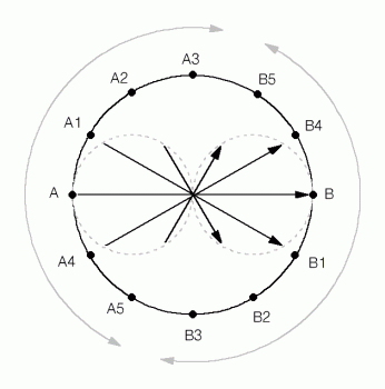
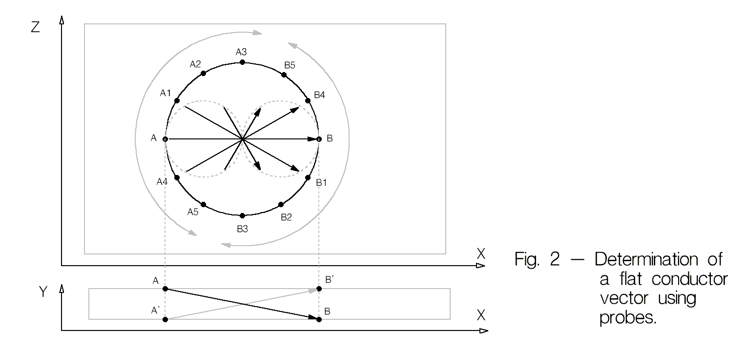
The vector of the plane conductor – is determined by its two orthogonal projections in two stages. First, an imaginary circle is determined on the surface of the conductor under study (projection \mathsf{X}\mathsf{Z} Fig. 2), the probes of the TAS are set at diametrically opposite points \mathsf{A} and \mathsf{B} on this imaginary circle and close the signal circuit of the TAS. Then, while remaining at diametrically opposite points, both probes simultaneously move along the circle without leaving contact with the surface, and during their movement, changes in the sound of the TAS are evaluated. After each of the probes has passed the semicircle, an arrow of the projection \mathsf{XZ} of the vector \overline{AB} is drawn on the surface of the foil, the beginning of which is determined by the point of contact of the output probe, and the end is the point of contact of the input probe at the moment when the clarity of the music sound is at its top quality. At the second stage, the projection of the vector \mathsf{XY} is determined, that is, the input and output surfaces of the test conductor are determined. Two variants \overline{AB} and \overline{A'B'} are evaluated, and the clearest one is selected. The resulting three-dimensional vector is constructed from the resulting two projections, and the part is marked in some convenient way. The marking is then used when assembling the electrical parts of the amplifiers in accordance with Contour system or mechanical parts according to the speaker cabinet diagram, the amplifier or other parts of the audio system.
Vector of the circular conductor – one end of the wire is clamped between the TAS probes and slowly rotated 360 degrees. During the rotation of the conductor, its position relative to the probes is determined when the clarity of the TAS sound will be the best. Thus, the transverse projection of the vector of one end of the wire is determined (Fig. 3 Left Side View). Then the same operation is performed at the other end of the wire. Then the longitudinal direction is determined with the corresponding TAS probes touching the found side input and output points of the conductor (Fig. 3 Front View).
In Fig. 3, vector \overline{AB} is the direction of the best sound of the wire, determined using the TAS. C, D, E, F – practically possible points of electrical contact (soldering) of the wire with neighboring components. In practice, the best possible result will be at contact along the vector \overline{CF} , the worst-through \overline{FC}, the variants \overline{ED} and \overline{DE} are intermediate. Without knowing these features, you can easily make a mistake while testing the wire, because although \overline{ED} and \overline{DE} are almost opposite in direction, they sound about the same because both are at a large angle to \overline{AB}. In the case of testing the wire through these points, the probability of correctly determining the direction of the wire is close to 50%. Interestingly, in a long wire, the angle a becomes almost zero, that is, \overline{CF} becomes almost equal to \overline{ED} , and \overline{FC} – equal to \overline{DE} , but the above features of the sound of a short piece of wire also manifest themselves well on a long piece.
Vector of dielectrics – is determined in the same way as for conductors, but after wetting its surface with water (read more here).
* – In order to avoid errors during tests, it is necessary to take into account the direction of the < em>vector of the TAS probes.
Psychic (tactile) option
Directionality is a phenomenon that defies the usual logical analysis. It is difficult for an outsider to believe that someone can feel the changes in the sound made by a single wire against the background of thousands of supposedly similar influences that exist in the system itself and existed during the recording of the audio medium. Skeptics rightly draw attention to this fact. In my opinion, audiophile hypersensitivity is akin to the super sense of smell of some animals, for example, the male butterfly Saturnia Pavonia, senses the smell of a female pheromone within a radius of 11 km. If we take into account that the concentration of matter in the air decreases in 3th power as distance increase linearly, then the probability of detecting at least one molecule of a tiny source of pheramone confidently tends to zero. However, the male somehow feels his mate. In the same way, I think, and music lovers are acutely react on some subtle melisms, which ordinary people do not care about. And apparently, the mechanisms of this sensitivity are much more subtle and immaterial than those that we are told about in biology lessons.
The intangibility of some audio vibrations confirms an interesting fact – the quality of the Coloration and the Direction of the component can be evaluated not only by ear, but also by touch. At the beginning of the research, only the TAS was used for tests, as described above, and it never occurred to me that the musical potential of the parts and wires could be evaluated in any other way than by ear. TAS regularly performed its functions for several years, until one day during the assembly of the transformer magnetic core did not happen a significant incident – before the test, the coil was soldered to the connectors J1 and J2 (see schematic on Fig. 1), but the switch SW2 remained closed, that is, the signal passed directly into the lamp grid bypassing the probes. The work was carried out as usual: the three-legged core plate was consistently inserted into the coil in four possible ways, its best position was selected by ear, then the process was repeated with the next plate, and so on. The closed circuit breaker was detected only after the testing was completed: the music continued to play when the coil leads were unsoldered from J1 and J2. The situation clearly hinted that all the differences found were just self-suggestion. However, the impressions during the tests were absolutely real, I could swear to this, and it occurred to me that the probes connected to the amplifier could somehow, for example, play the role of an antenna. It was decided to double-check the result – the plates were marked with paint, then the magnetic core was disassembled and assembled blindly again with SW2 open. The new result was 80% the same as the previous one! There was no end to my surprise then, but it was only the beginning.
The next amazing moment opened up in the process of finding an answer to the question of how serial errors can occur in the classic test of conductors with TAS. For example, in mass testing with the help of TAS, 10 times the result could be correct, then there could be 5 incorrect results in a row, then the correct results again went on. After much agony, it became obvious that most of the errors were caused by my hands, namely, how the test probes were held during testing. My hands turned out to be energetically unsymmetric, the left hand was the pronounced output, and the right hand was the < em>input. System errors has been a thing of the past, when the output probe J1 was held in the left hand, and J2 – in the right.
After some more time, I was faced with a very incredible fact – it turned out that when you performing TAS tests the probes are not needed at all – you could just turn on the music, turn the part around in your hands and find its most natural position between your palms or fingers. Thorough echeck showed that in this case, the beginning of the component was located on the left hand side, and the endwas located on the right hand side. It was an emotional jolt of overwhelming force.
The next discovery finally turned everything upside down – during the next tests using just hands, I accidentally discovered that it was not necessary to turn on the music at all, the direction and overall musical quality of the component could be felt just as confidently in complete silence. Checkmate for materialism.
Properties of vectors
- Vector orientation is characteristic of all solid objects, both man-made and unprocessed, natural materials.
- Directionality manifests itself not only in audio, but also in in optics.
- In plants, the vector is directed in accordance with the changes in their size during their growth, that is, from the roots to the crown and from the core to the surface (Fig. 4).
- The coincidence of the vector direction of a factory-made component with its longitudinal axis is a rare, special case. No direct connection between the vector direction and the geometric shape of the factory components was found.
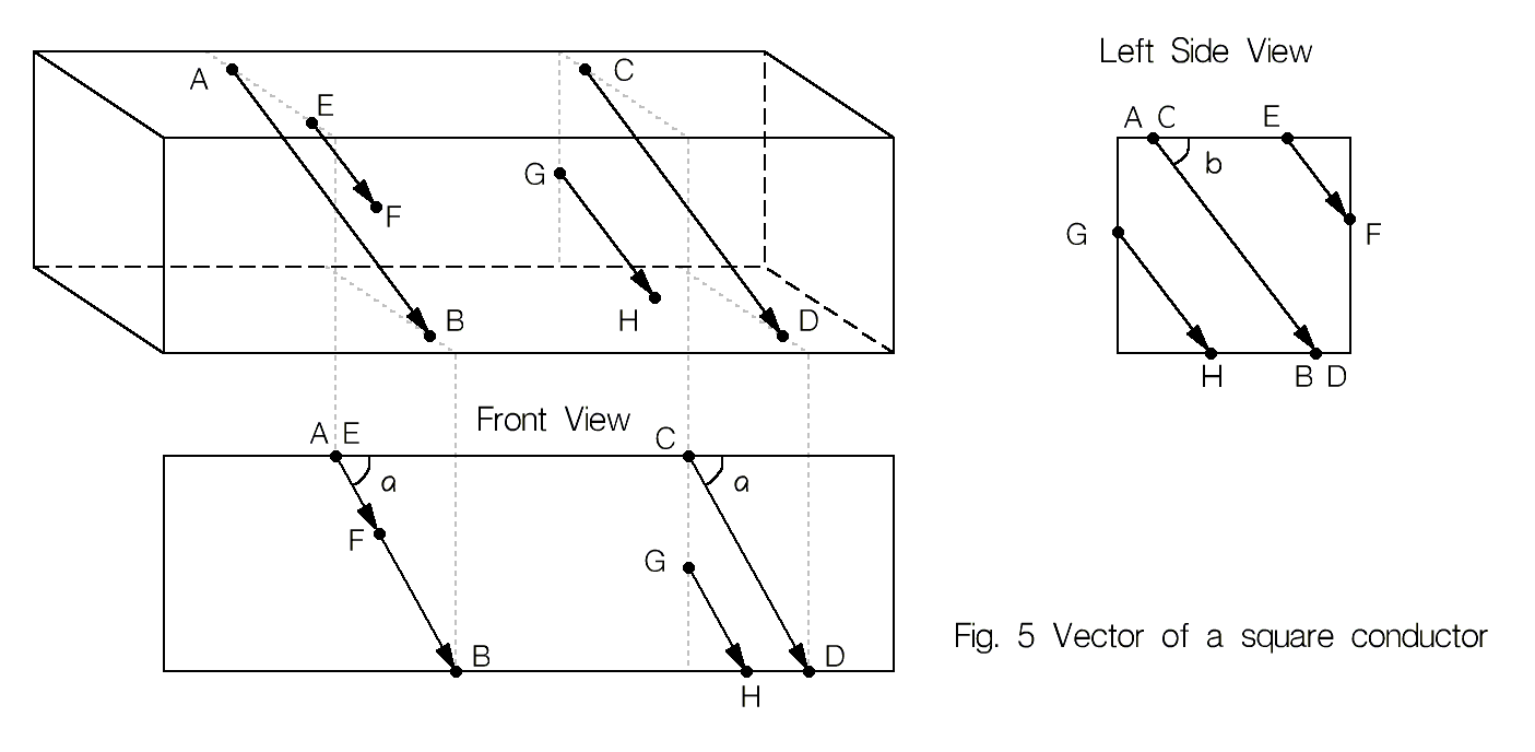
- WIth other things being equal, unidirectional collinear vectors sound the same, so in each simple component we have an uncountable number of pairs of input and output points, with zero vector losses. In Fig. 5 \overline{AB} \equiv \overline{CD} \equiv \overline{EF} \equiv \overline{GH}
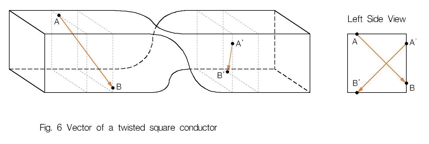
- When bending or twisting a wire, metal plates, etc., their vector bends and twists exactly repeating the distorted shape of the component (Fig. 6), while if you then restore the shape of the component, the direction of its vector is also restored.
- In the directions perpendicular to the vector (see Figure 2, the zero vector \overline{A3B4} ), the directivity of the component is absent, while the sound of the component becomes averaged with respect to the vectors \overline{AB} and \overline{BA} .
- Vectors do not change their orientation relative to the geometric shape of the radio components, either under the influence of a direct electric current or under the influence of a magnetic field.
This observation is based on a thorough study of old, mostly pre-war radio components: transformers, condensers, vacuum tubes, wiring of electrical appliances, both direct and alternating current, which have worked for decades in the same “electro-magnetic conditions”. The conductors and dielectrics from which the long-used radio components were assembled, from the directivity point of view, were always connected without any system, for example: the direction of the transformer terminals almost never coincided with thedirection of their windings, and the wiring, including the segments of the conductors from which the tubes, resistors and capacitors were assembled, never corresponded to Electrical Contours and contained both direct and counter-inclusions of the conductors.
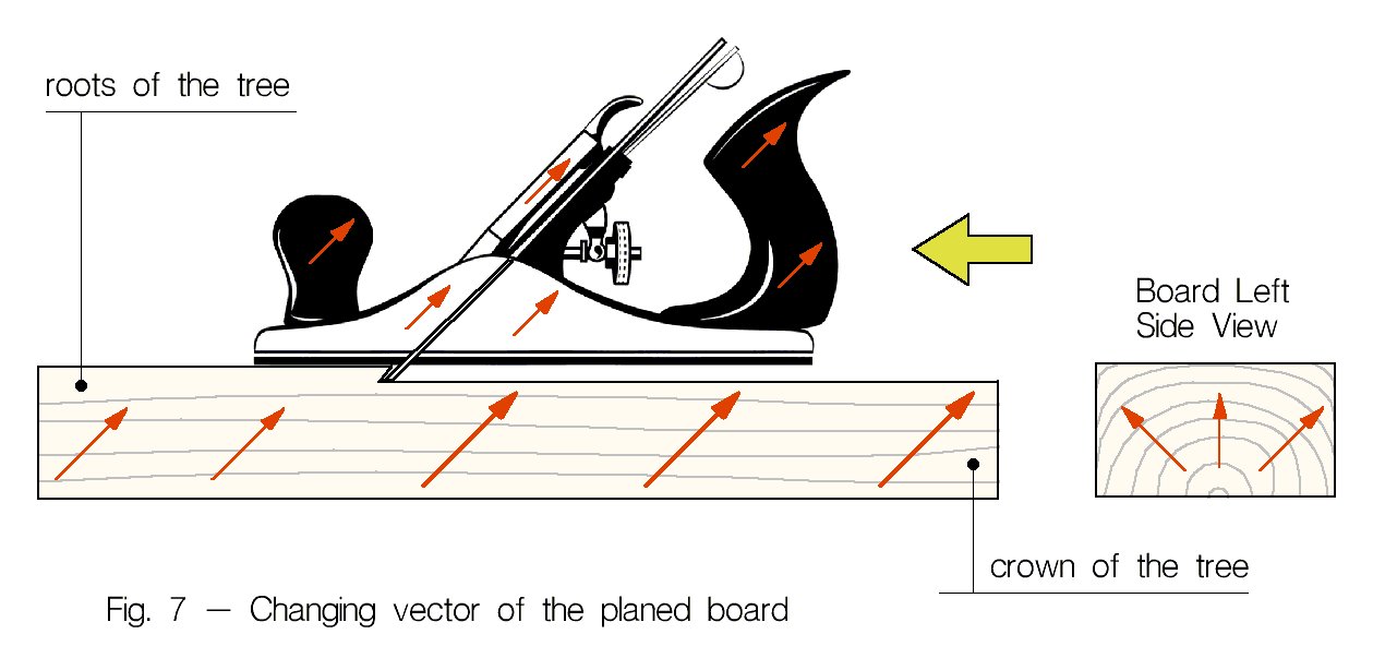
- Mechanical treatment of the surface of the components (sawing, planing, grinding, etc.) causes the appearance or correction of the Surface Vector (SV). Fig. 7 shows the correct orientation of the board and plane when planing: the plane, the board, and the right (input) hand pushing the plane should be co-directed, only in this case there are no vector losses during processing. Also, mechanical processing has a significant and stable effect on Coloration and other intangible properties of the components (read more here).
The direction and strength of the total vector of a group of components can be estimated by the mathematical rules of adding the vectors of individual components that are included in this group.
Rotation vector
The rotation vector (RV) determines the progressive and tangential direction of the winding of the conductor relative to the direction of the conductor and the longitudinal direction of the frame or other element on which the conductor is wound. RV must be taken into account when winding transformers, inductors, wire resistors, rolled foil capacitors. The RV is perpendicular to the plane of rotation and is related to the direction of rotation by the right-hand rule.
 “If you take the frame of the inductor with your right hand so that the straightened thumb points towards the longitudinal direction of the frame, then the wire should be wound on the frame along four curling fingers. The beginning of the wire should be located at the little finger, the coil is wound from the little finger towards the index finger”
Radius Vector
The radius Vector (RV) is formed in multilayer inductors and rolls of capacitors, is inherent in all plants in nature and is directed from the center to the outside (see Fig. 4). The RV of inductors or coil capacitors should also be directed from the center to the outside. To form RV with this direction, before winding the component, make sure that in the reel from which you will reel off the wire or foil, the beginning of the wire (foil) is located outside. If this is not the case, then the source reel must be rewound to an empty reel and only then wind the coil of the future transformer or the capacitor plate. For capacitors in addition, the input and output surfaces of the foil have to be determined (see Figure 2 – < a href="#fcv">vector of the flat conductor). When winding, the input surface of the foil should be located closer to the center of the roll. Vector Radius Rule:
Forming a vector with a given direction
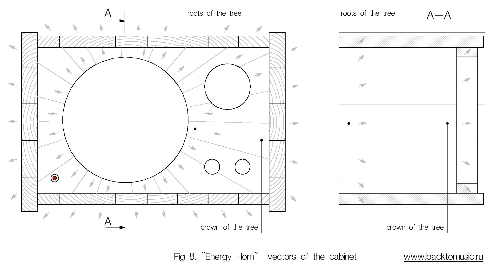
At home, you can form a vector for low-melting metals (lead, tin, aluminum), as well as for dielectrics (waxes, resins, lacquers and paints). It is also possible to assemble an object with the necessary properties from parts with a known orientation, for example, to glue the speaker body (Fig. 8). It is known that the stable, vector orientation of metals and dielectrics is formed at the moment of their transition from a liquid state to a solid, presumably – under the action of some intangible Vector Field (VF) that surrounds us. At the moment of its transition from the molten to the solid state, the component “remembers” the state of the VF that crossed it and remembers it until it is melted again. A person (me personally) has a strong and stable source of the VF – these are the hands. The degree of influence of other parts of the body varies under the influence of various, poorly predictable circumstances. It is not yet possible to say anything about the conscious and purposeful use of the VF of a person in audio, but there is no doubt that a person has a tangible impact on the sound of the audio system that he makes, regardless of whether he wants it or not. The VF of each object, as well as the VF of a person, affects the formation of directivity in objects located next to it, which at this moment pass from the molten state to the solid state. Thus, we can talk about the presence of Vector Fields of different strength and configuration emanating from all the objects around us. The influence of VF of objects on the formation of Vectors of solidifying liquid materials located next to them is proportional to their current strength and inversely proportional to the distance between them.
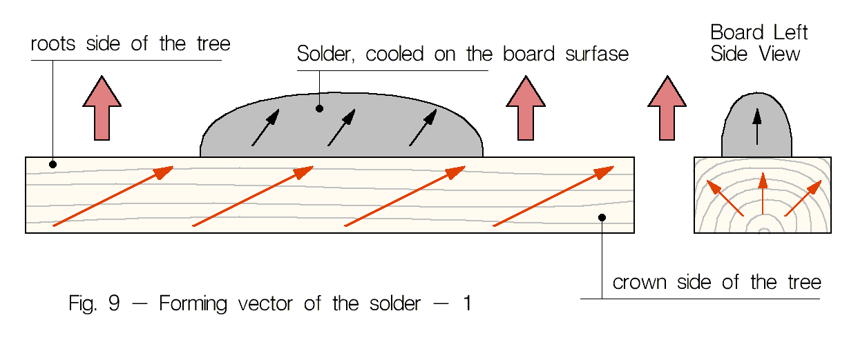
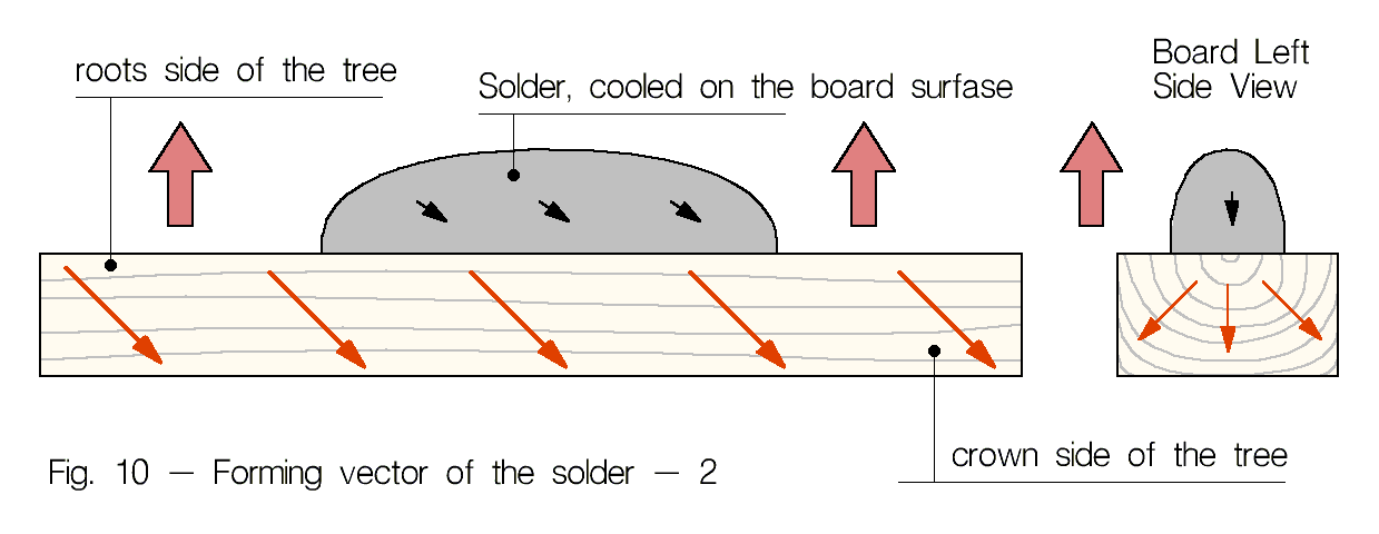
There is at least one source of the VF, the influence of which does not depend on the distance to any object in the room. This field, in the case when it is not counteracted by the field of foreign, closely located objects and/or a persons, forms a stable vector with a bottom-up direction for solidifying objects. The presence of this field was deduced logically when it became clear that during experiments on the directivity formation of radio components, each time a certain correction of the vector in the bottom-up direction is tracked. It is possible to compensate for this bottom-up influence (that is, to deflect it to the side or change it to the opposite direction) only if the solder freezes on a massive board or piece of metal whose vector is directed downwards. Perhaps this bottom-up influence is the influence of the Earth’s VF.
Fig. 9 and Fig. 10 show two variants of the formation of a vector in a drop of solder solidifying on a wooden board. The bold red arrows show the Earth Field, the normal arrows show the vectors of the board and solder, after it has solidified. The sound of the solder in Fig. 10 turns out to be unformed, dull and it is difficult to determine the correct direction on it. The pure sound of the solder will only be obtained if the vector of the object on which the solder was frozen al least roughly coincided with the direction of the Earth’s field (Fig. 9).
Conclusion
Vector orientation can be safely called a theory, since it combines disparate, subjective facts (both auditory and visual) into a single system and explains the poor repeatability of many subjective experiments, allowing them to be made repeatable.

