
Push-pull amplifiers and rectifiers in comparison with their single-ended versions have two significant drawbacks — a complex design that causes loss of sound clarity and the inability to comply with the four rules of orientation of transformer parts:
- Coil wire orientation: the wire directions must fit in the Contour System.
- Right-hand rule: sets the direction of winding the wire clockwise relative to the vector of the central core of the magnetic core.
- Spatial position of the coil: the axis of the coil should be located vertically, and the total vector of the components of the coil is directed top-down
- Vector of the magnetic core iron: relative to the windings, the direction of the central core is also determined by the right-hand rule.
Thus, on the one hand, to make a transformer with a clear sound, it is necessary that all its windings are wound according to the right-hand rule. On the other hand, if we look at the circuit of a push-pull amplifier, we will see that in order to match the directions of the transformer wires to the circuit system, one of the windings will have to be wound vice versa — according to the left-hand rule. Otherwise, if we wind all the coils according to the same rule, the system of Contours will be violated.
In the explanatory figures, the bold black lines and arrows show fragments of the Contours, the red arrows indicate the directions of the transformer windings, and the gray ones indicate the vectors of the magnetic core.
Fig. 3 shows a variant where the magnetic core vector, by analogy with the Contours, is closed in a circle. Such a circular orientation was hypothetically derived at a time when it was impossible to conduct a more or less accurate experiment with cores and it was not yet certain that the conductors’ directivity did not correlate in any way with the current flow or other physical quantities.
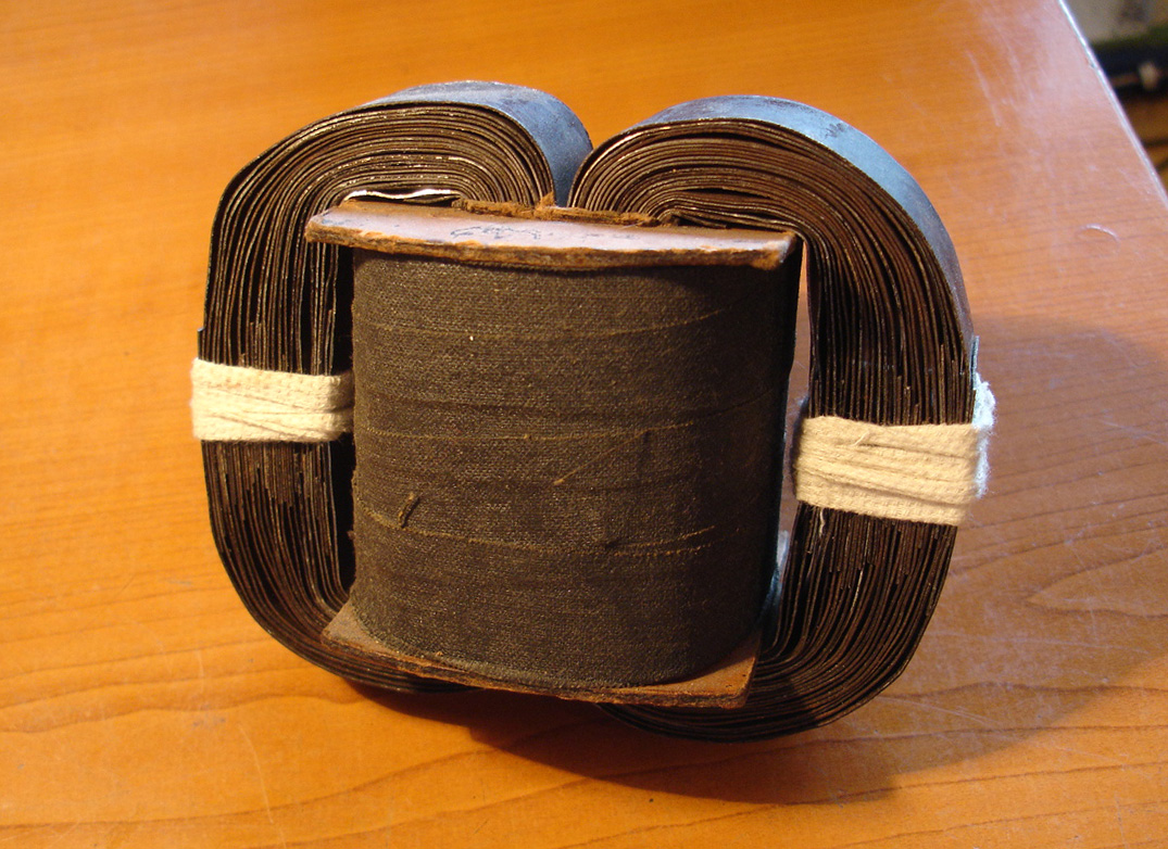
The first real steps to investigate the directivity of magnetic cores were made using Testing Audio System (TAS) on an inductor with flat, iron bands used as a magnetic core. First, the TAS was used to determine the longitudinal direction of all the band, then the coil was connected to a testig socket of the TAS and during listening to music, the bands were inserted one by one into the coil. Changes in the sound of the TAS were monitored by ear and for each plate, its best position out of four possible was determined. At the end of the experiment, it turned out that more than 80% of the plates were longitudinally directed relative to the coil according to right-hand rule .
At the next stage, two symmetrical versions of the core were assembled (Fig. 4 and Fig. 5), in which the central core in relation to the winding was directed according to the right-hand rule. In the figures, the gray arrows show the direction of the plate vectors, the black arrows show the total spatial direction of the winding, and the red arrows show the longitudinal direction of the wires. Both options sounded significantly worse than the option with the simplest i-core, but the reason for the bad sound could be not only in the circular orientation of the magnetic core. During the experiment, when the plates were successively bent, the clarity of the sound of the TAS gradually decreased, but this could be attributed to vector-losses, and not to the core vector being closed in the ring. In another experiment, during the assembly of a conventional three-leg core transformer, it was also possible to choose the best position for each of its ш-plates, and similarly, when adding plates, clarity gradually decreased even after choosing their optimal position. In this situation, it was impossible to say with certainty which design was better, it was only possible to say which of these two specific transformers by the sum of the pros and cons sounds preferable without any generalizations.
The question of the preferred direction of the magnetic circuit in relation to its windings remained unresolved, the optimal sound solution came later and from the reverse side — from the chassis and cabinet.
To ensure that the sound of the active speaker (AS) is not clamped when the amplifier is installed in it, it is necessary that all the components of the amplifier are maximally co-oriented with the bottom of the speaker cabinet. The bottom and the chassis mounted on it are made with the direction from the inside out and at the viewer. If you look at the transformer in Fig. 4, it becomes clear that it is impossible to co-orient it with the chassis, since the vectors of both its halves are directed inward. A variant of Fig. 5 will lose less in sound, but, anyway, it still can not be installed without serious vector losses in one of the halves of the core. The situation will be even worse if you want to rigidly fix the transformer to the chassis with the help of the upper bar and two long bolts (the best, simplest method of fastening), in which case we will get three almost opposite direction touches out of four, which is completely unacceptable.
The analysis of the situation shows that the only version of the core that allows you to fully reveal the sound of the transformer is a two-legged «O» core, the vector of which has the same direction in all its sections and is as accurately aligned with the Vector of the chassis as possible — Fig. 6. The analogy here can be continued further: the vector of the chassis should be co-directed with the Vector of the speaker cabinet, the cabinet with a rack for equipment, and so on. Ideally, the housing, chassis, transformer and all other parts installed both inside and outside the amplifier and speaker should be a single unit.
The assembly and co-directional orientation of the magnetic core parts and a chassis allowed us to solve two seemingly unsolvable problems:
- Rigid attachment of the transformer to the chassis with co-directional mounting brackets without loss of sound clarity.
- Simultaneous compliance with all four of the above rules when winding, assembling and mounting a push-pull transformer with an two-legged magnetic core.